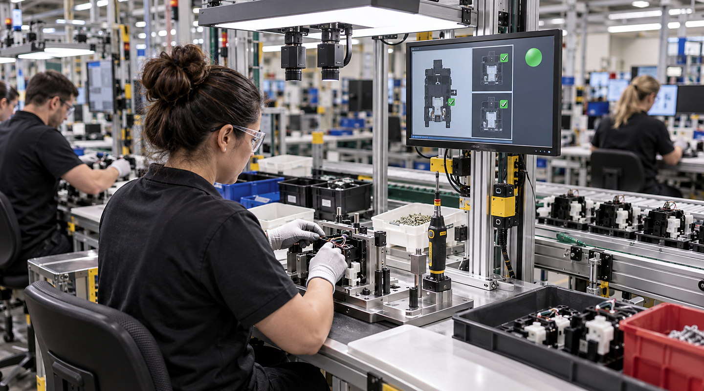
Plan solder joint inspection around representative good, bad and marginal samples, line presentation, lighting, reject handling and challenge criteria. Discuss an optical feasibility trial with Oxford Vision Systems.
Speak directly with Oxford Vision Systems about visible solder-joint inspection.
In brief
Choose solder joint inspection by defining visible defect or measurement definition for visible solder-joint inspection, good, bad and marginal sample range, optics, lighting and environmental conditions, and false-accept, false-reject and challenge criteria, then prove the preferred method using representative good, bad and marginal samples before the final system is specified.
Your final solder joint inspection scope must also account for recipe, reject and line-control interfaces, false-accept, false-reject and challenge criteria, current regulations and the conditions at your site.
Quick answer
Which solder-joint defects are visible to an optical inspection system?
For solder joint inspection, define visible defect or measurement definition for visible solder-joint inspection and collect good, bad and marginal sample range before choosing cameras. An optical trial should prove contrast, presentation and timing, followed by agreed checks for false-accept, false-reject and challenge criteria.
Six useful questions
Describe what you need from solder joint inspection before choosing a solution
For in-line inspection using visible solder-joint inspection, share the normal condition, realistic range and difficult cases the finished system must handle.
Question 1
Visible Defect or Measurement Definition for Visible Solder-Joint Inspection
For your initial enquiry about solder joint inspection, describe the current position, required outcome, acceptable limits and known exceptions for visible defect or measurement definition for visible solder-joint inspection. That lets us compare options against your real production rather than one nominal value.
Question 2
Good, Bad and Marginal Sample Range
For your initial enquiry about solder joint inspection, describe the current position, required outcome, acceptable limits and known exceptions for good, bad and marginal sample range. That lets us compare options against your real production rather than one nominal value.
Question 3
Part Presentation and Production Speed
For your initial enquiry about solder joint inspection, describe the current position, required outcome, acceptable limits and known exceptions for part presentation and production speed. That lets us compare options against your real production rather than one nominal value.
Question 4
Optics, Lighting and Environmental Conditions
For your initial enquiry about solder joint inspection, describe the current position, required outcome, acceptable limits and known exceptions for optics, lighting and environmental conditions. That lets us compare options against your real production rather than one nominal value.
Question 5
Recipe, Reject and Line-Control Interfaces
For your initial enquiry about solder joint inspection, describe the current position, required outcome, acceptable limits and known exceptions for recipe, reject and line-control interfaces. That lets us compare options against your real production rather than one nominal value.
Question 6
False-Accept, False-Reject and Challenge Criteria
For your initial enquiry about solder joint inspection, describe the current position, required outcome, acceptable limits and known exceptions for false-accept, false-reject and challenge criteria. That lets us compare options against your real production rather than one nominal value.
Applications
Two useful starting points for solder joint inspection
The right choice changes with visible defect or measurement definition for visible solder-joint inspection, good, bad and marginal sample range, your line layout and required results.
Your route from an initial enquiry to a working solution
You can review decisions about recipe, reject and line-control interfaces and false-accept, false-reject and challenge criteria at each stage.
01
Define the Visible Decision and Collect Representative Samples
Share representative good, bad and marginal samples, including the normal range for visible defect or measurement definition for visible solder-joint inspection and the difficult good, bad and marginal sample range cases.
02
Prove Contrast, Presentation and Timing in an Optical Trial
Compare suitable methods and use focused trials to show how each option performs against part presentation and production speed.
03
Integrate Cameras, Controls, Reject Handling and Recipes
Connect the equipment to your line, services and controls while resolving optics, lighting and environmental conditions for day-to-day operation.
04
Challenge Marginal Cases and Document Agreed Results
Confirm recipe, reject and line-control interfaces, then complete and record false-accept, false-reject and challenge criteria before your operating team takes over.
Important limits
Know what needs a separate check
A camera can only assess a property made visible and repeatable by the inspection setup.
Sample diversity and marginal cases determine how meaningful a feasibility result is.
Visual inspection does not replace hidden, destructive, functional or statutory tests.
Your final solution for visible solder-joint inspection must reflect the law, current standards and site-specific risks that apply to your installation.