Compare practical options for visible solder-joint inspection, including what each route needs, where it fits and what to check before you decide.
In brief
The right solution for solder joint inspection is the simplest system that reliably handles your stated duty, line connections and expected exceptions.
Plan solder joint inspection around representative good, bad and marginal samples, line presentation, lighting, reject handling and challenge criteria. Discuss an optical feasibility trial with Oxford Vision Systems.
On the production floor
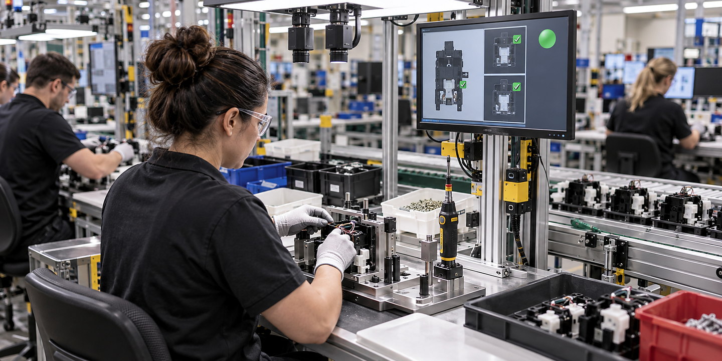
See how the complete system fits your production line — Solder Joint Inspection
Plan solder joint inspection around representative good, bad and marginal samples, line presentation, lighting, reject handling and challenge criteria. Discuss an optical feasibility trial with Oxford Vision Systems. When you compare solutions, check how each option handles visible defect or measurement definition for visible solder-joint inspection, good, bad and marginal sample range and your surrounding line.
Solder Joint Inspection support from first review to production use
Understand your requirement
Review visible defect or measurement definition for visible solder-joint inspection, good, bad and marginal sample range, and part presentation and production speed using your samples, drawings and production observations.
Compare suitable approaches
Run focused trials for solder joint inspection so you can see why an option is recommended or ruled out.
Fit the complete line
Resolve optics, lighting and environmental conditions, recipe, reject and line-control interfaces, controls, safety, operator access and maintenance before site work.
Prove and support the result
Check false-accept, false-reject and challenge criteria in normal, difficult and fault conditions, then agree training and support for your team.
Typical support: defect definition, sample study, optical trials, enclosure and reject integration, and challenge validation.
Compare your options
Compare solder joint inspection with simpler routes
Approach
Often suitable when
Watch for
Solder Joint Inspection
You need a dedicated solution for a clearly defined duty, product or part range and line interface.
A camera can only assess a property made visible and repeatable by the inspection setup.
Purpose-Built Sensors for Simple Presence or Position Checks
The required decision is a simple presence or position check and a trial shows that an appropriate sensor can distinguish the stated condition.
A presence or position signal does not establish solder-joint quality. Check the actual decision and normal variation; retain separate inspection or testing for properties the sensor does not assess.
Offline Metrology or Destructive Tests where the Property Is Not Visible Inline
The required property cannot be assessed from repeatable in-line views, so the quality team needs to consider an appropriate separate measurement or test method.
Define the property, method, sample coverage and decision responsibility separately. An optical result cannot establish a hidden-joint or functional result, and a sample-based test does not inspect every production assembly.
What to send us
Help us give you useful guidance
Representative Good, Bad and Marginal SamplesInclude the current revision and explain what this information should show for your operation.
False-Accept and False-Reject Challenge ResultsInclude the current revision and explain what this information should show for your operation.
Lighting, Recipe and Reject-Response RecordsInclude the current revision and explain what this information should show for your operation.